Lewis Hamilton’s First F1 Victory: Mastering Montreal’s Braking Challenge
October 14, 2024
by Rowland Jowett
Discover an untold story behind Lewis Hamilton’s first race victory in 2007 and explore how modern simulation technology could have simplified this monumental achievement.
I remember vividly my first day at McLaren Formula 1 as a dream come true. Touring the world-class facilities, historic cars, and gleaming trophies felt more like stepping into a high-tech semiconductor plant than a car factory. After a surreal breakfast and champagne toast for the weekend’s race victory, reality quickly set in. The office tour revealed anxious faces and urgent greetings: “We’re so glad you’re here, it’s Canada soon and there’s a lot of work to be done…” This set the scene for what lay ahead.
2007 represented one of F1’s most historic battles between the defending double world champion Fernando Alonso and F1 rookie Lewis Hamilton. To deliver this display to fans an enormous engineering effort took place behind the scenes. At the time I had been recruited to work on the brakes and McLaren did not have a solution to get through the toughest circuits without a failure. Now I reflect on this moment and wonder if this physical problem could have been fixed using simulation solutions to produce an even quicker car.
The Braking Challenge of Montreal Circuit
The Montreal circuit, characterized by its long, fast straights and six heavy braking zones leading into tight chicanes or low-speed hairpins, poses a significant challenge for brake management. The brake cooling ducts, strategically positioned behind the front wing for aerodynamic efficiency, unfortunately, receive suboptimal cooling air, a particular issue for the 2007 car. Ensuring the brakes remained functional throughout the race required meticulous preparation…

Circuit map of Montreal showing brake power in major braking zones
Brake Energy and Cooling
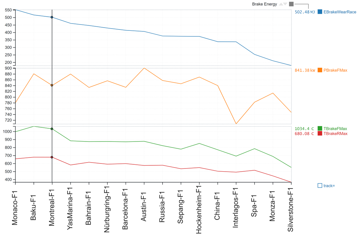
Using Canopy/Michelin laptime simulation, we can run laps around every circuit on the F1 calendar and rank each by race brake energy, as shown in the graph below.
At the Montreal circuit, the braking system needs to dissipate a staggering 502MJ over the race, with an average power of 99kW and peaks reaching 841kW. This makes Montreal the most demanding circuit of its time, requiring more than double the braking effort compared to Monza. Although Baku has since surpassed Montreal in braking demands, the Canopy thermal model reveals a 482°C increase in brake temperature at Montreal compared to Silverstone under the same cooling conditions. This data is crucial for appropriately sizing brake ducts.

Selection of F1 circuits in order of brake severity
Insights from Other Circuits
Monaco ranks as the highest brake energy circuit but due to its shorter straights and lower speed characteristic, peak brake power and consequently wear is reduced. However, the circuit’s tight layout and reduced average speed hinder cooling efficiency. Additionally, following closely in traffic introduces dirty air into the brake ducts, increasing the risk of caliper overheating. Before advanced thermal laptime simulation, we used a rule of thumb: Monaco resulted in +40°C caliper temperature compared to the next worst circuit. The caliper, close to a disc peaking at 1000°C, needs to be cooled to less than 240°C to avoid melting piston seals and leaking brake fluid.
Advanced Brake Technology
F1 brakes are made from exotic carbon-carbon material, akin to carbon fibre but bonded with a carbon matrix, they offer superior temperature resistance and are lighter than the carbon-ceramic brakes found in supercars. These discs wear through oxidation of the carbon matrix as they glow red hot, turning into CO2 and leaving tougher carbon fibres exposed, which are then worn off by mechanical action, leaving a puff of brake dust. Disc wear can be up to 16mm in a race with the friction material left held together by the scarce material surrounding a thousand radial ventilation holes. Displacement sensors on the caliper pistons measure live brake wear for the race engineers to monitor during a race, and it is important to have a plan B in case of excessive wear. Retiring from first place in Abu Dhabi (next in the rankings to Montreal) due to excessive brake wear was highly embarrassing, hence the need for careful preparation using simulation.

Image from brake dynamometer
The Expensive way to Win
Working at McLaren on a championship-winning car involves careful performance trades, accurately evaluated using laptime simulation. The trade between aerodynamics and brake cooling was critical. At the time, we didn’t use simulation for this trade so the best option involved back-to-back shifts in the brake dynamometer testing machine, burning tens of thousands of pounds worth of exotic material to find one that could withstand over 1000°C for a race stint. This knowledge was invaluable, helping Lewis to secure his first F1 victory in Montreal 2007.
Modern Solutions with Canopy/Michelin Laptime Simulation
In the modern era, a Canopy subscription provides a cost-effective and far more versatile alternative to brake dynamometer testing. This simulation technology could allow drivers to use softer, more easily modulated brakes without losing aerodynamic efficiency from bigger brake ducts. Earlier in the season, Lewis Hamilton finished 2nd in Bahrain without annihilating his brakes, so what would it take to reduce the brake energy at Montreal to this safe level? In Canopy, a brake saving simulation can be run by adding brake wear as an objective function constraint in addition to minimum laptime.
Dynamic Lap and Brake Energy Management
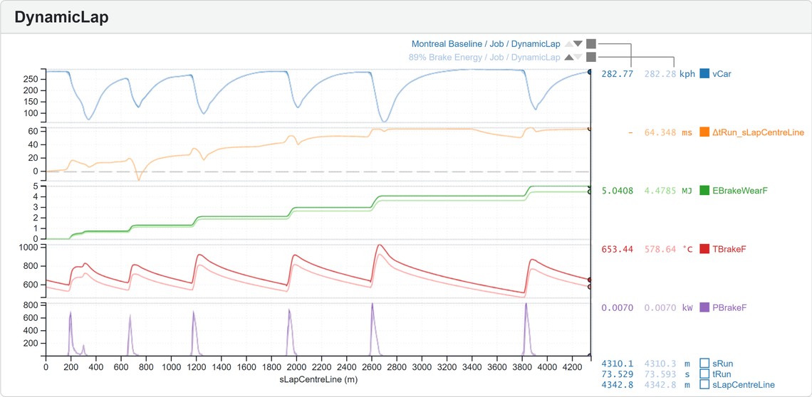
Dynamic Lap simulation provides the most efficient way to achieve this energy target. The graph below shows a flat-out simulated lap of Montreal and another with an 89% brake energy limit (same as Bahrain). This reduces the most damaging peak brake temperature by 106°C for a laptime difference of just 64ms, offering a viable race completion strategy or backup plan for the sake of just 10 minutes of simulation work.

Overlay comparing flat out lap of Montreal with 11% brake saving
Optimal Driving Techniques
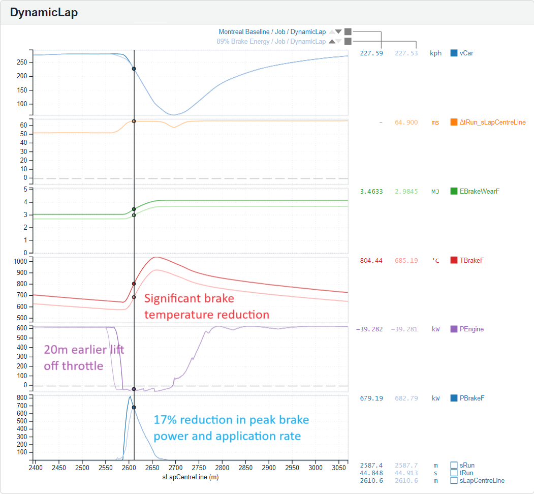
This brake saving strategy is achieved by lifting off the throttle on average 20m early with simulation providing the precise lift off point bespoke to each corner and reducing brake pedal application rate to limit peak power to 83%. Dynamic Lap Secondary Laptime Sensitivities show why this is an efficient strategy, essentially losing time on entry is OK, provided the driver gets a stellar exit and maintains performance down the next straight. Driving less aggressively might not sound exciting, but this 64ms represents the worst-case scenario before other trades have been considered. The fuel saving alone from lifting slightly early might present a strategic advantage large enough to wipe out the headline laptime loss.

Optimal Brake Saving Strategy Zoomed into Hairpin
Further investigations
In F1, compromise is not about settling for less; it’s about maximising performance across all aspects on the Pareto front. For instance, how does brake saving compare to fitting a larger, draggy brake cooling duct? Simulation can help quantify these trades and many others to improve upon the worst-case brake saving, and make a car that is significantly quicker than the initial car. Some of these examples shall be explored in further detail in other articles:
Exploring fuel savings: Investigate the impact of early lifting, which here results in a significant 2.3% fuel saving. Future articles will explore whether the weight savings from modest fuel saving lead to quicker overall stint times.
Repeating the aeroscan with brake saving: Simulate every wing option and configuration to find the quickest setup with brake saving enabled. Coincidentally, Montreal’s isochronal ratio matches the typical lift-to-drag ratio of downforce packages, allowing teams to run low or high downforce with similar lap times. Enabling brake saving might shift the trade in favour of higher downforce due to lower end-of-straight speeds and higher apex speeds, resulting in less braking.
Parameterising brake performance: Model the hardest-wearing brakes in a Canopy-equipped DiL to quantify drivability loss by running brakes that are harder to control.
Mapping brake wear: Use Canopy to map brake wear as a function of temperature and pressure, optimising directly for wear saving instead of using brake energy as a proxy.
Investigating tyre thermal performance: Use the Michelin TAME thermal and mechanical tyre model to explore the impact of modest brake saving, which can reduce tyre sliding energy by 2.5% on initial braking. This reduction can lower tyre temperature both directly from sliding and indirectly from reduced brake heating through the rim. Advanced thermal simulation can determine if this approach is quicker for a stint.
Optimising mechanical setup: Develop a car setup that shifts the preferred brake balance to the least critical axle. This concept, explored with tyre saving, not only demonstrates the best driving techniques but also delivers a setup that is quicker and more sympathetic.
In the fiercely competitive world of F1, where technology advances rapidly, it is valuable to pause and consider how past challenges could have been addressed more effectively. Utilising today’s advanced simulation tools could have significantly simplified these engineering battles, making the pursuit of optimal performance much more manageable.
Conclusion
Lewis Hamilton won the Montreal GP, thanks in part to the extensive brake dyno work required to find the hardest wearing material known to man. In retrospect could this victory have been made easier using laptime simulation-based solutions instead? Yes, had the technology existed then simulation seems like a more efficient approach. Race engineering is fundamentally about finding the optimal set of compromises, and laptime simulation is a powerful tool for achieving these trade-offs. It maximises performance on the Pareto front, ensuring balanced performance across all departments. Stay tuned for more insights and advancements in this exciting field.