How to balance an F1 car through the corner
SEPTEMBER 14, 2017
Imagine you’re the race engineer for <insert your favorite driver name> and your aerodynamics department have just spent 3 months working on a new upgrade, your driver runs it and says: “it’s completely undrivable, there is too much understeer in low speed mid corner but I cannot add front wing because high speed will become nervous, and entries to low speed are unstable”.
This is the classic problem of poor through corner balance which can really hold the driver back in being able to exploit the maximum performance from an upgrade. One way to help alleviate the problem is to change mechanical balance through the corner. This could be done by changing the anti-roll bar (ARB) geometry. Here we’ll take a look at the effect of changing the ARB pickup inboard.
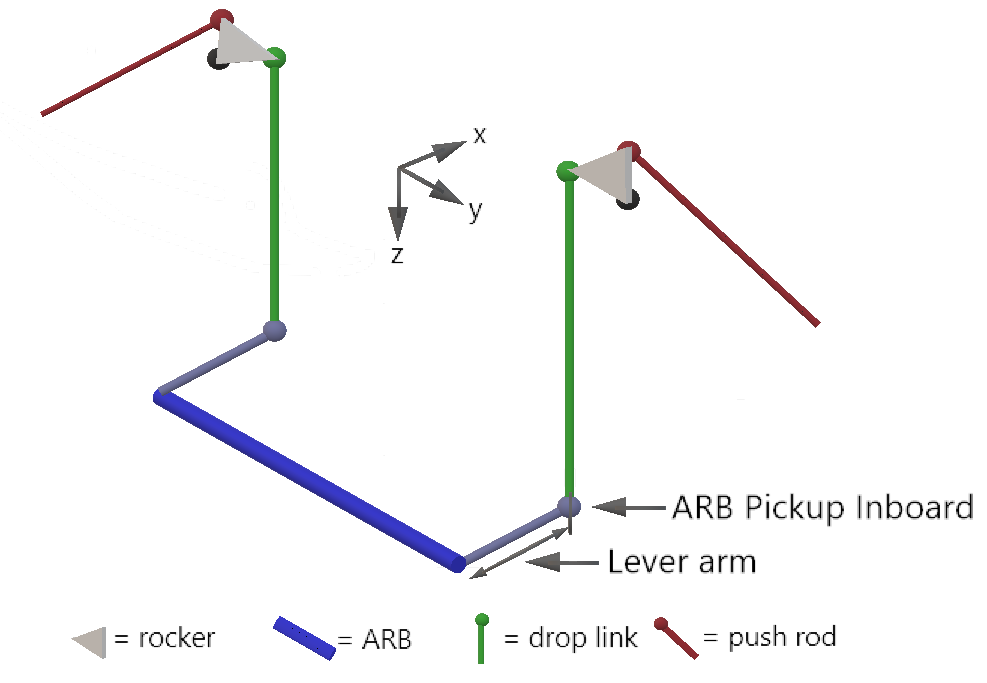
Figure 1: U-type Anti-Roll Bar Topology
Firstly we’ll look at the effect of displacing the ARB pickup inboard in the both x and z. We can do this by running 2,000 simulations which explore the effect of changing this aspect of the suspension geometry. In Canopy we call this an “exploration” — we’re literally exploring the effects of varying any number of physical parameters on the performance of the car.
By changing the pickup point in x and z, we alter the kinematics which will affect the ARB lever arm length so we’ll also throw the front and rear ARB stiffness parameters into the exploration to allow us to compensate for this.
Once you’ve run 2,000 simulations it’s not much use going through them one by one to find one you like, so we’re going to use some of our visualisation tools to understand the effects of our geometry changes. Figure 2 shows the parallel coordinates plot which we’ll use to help us target the interesting regions.
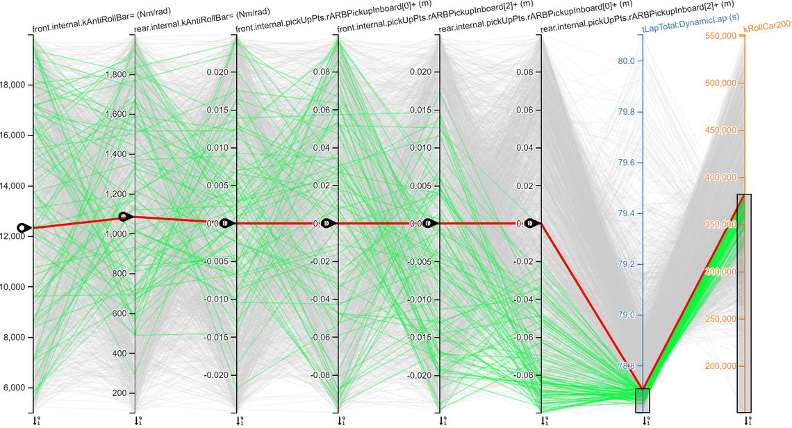
Figure 2: First look at the results
Here we see our 6 simulation parameters (ARB stiffness at both the front and rear, x and z displacement of the ARB pickup inboard point) and only a couple of simulation outputs to keep things simple (laptime and roll stiffness). We can move the red line to explore the results surface and infer the output for combinations which haven’t been run. In this case the red line has been moved to represent the baseline car setup. We’ll then highlight only the results with the quickest laptime. We don’t simulate ride performance (yet!), but we want to make sure we’re not making the car too stiff by highlighting only the simulations which have an overall roll stiffness less than or equal to the baseline. We can see that there are a number of runs which satisfy this criteria and are quicker than the baseline, so we’ll do some further investigations.
If we repeat the exploration for the front only, we can only improve upon the baseline laptime of 78.71sec by a few ms (spoiler: the range of front heave travel is too small for the region we are exploring front ARB geometry in), therefore the improvement must be coming from the rear. Repeating for the rear on its own shows a potential improvement of 54ms. While this might not seem like much, the ability to consistently pick up chunks of performance like this is what separates the great teams from the rest. We can see from the parallel coordinates chart that this is achieved by moving the ARB inboard pickup upwards and rearwards (-ve rARBPickupInboard[2] and -ve rARBPickupInboard[0]) with a softer ARB to compensate for the reduction in lever arm. The resulting geometry is shown in Figure 3:
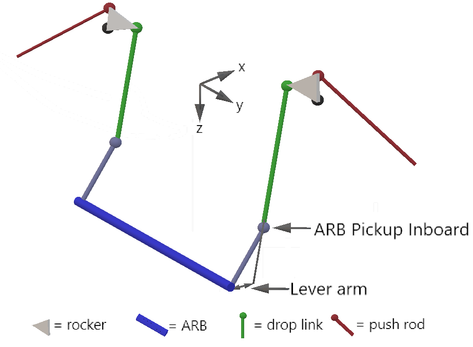
Figure 3: ARB Pickup Inboard moved up and rearwards at setup
This looks very similar to simply rotating the ARB at setup (car stationary at 0kph), which would be very easy to achieve by shortening the green drop link; so we re-ran the exploration, but instead of allowing the ARB pickup inboard to have freedom in the x-z plane we restricted it to the arc constructed from the rotation of the ARB. We find that an initial rotation of the ARB of 60deg up from horizontal (as shown in Figure 3) and a softer ARB to compensate improves our laptime by 51ms, so we gain most of the benefit but only need to modify the drop links.
What effect does this have? Due to downforce, the rear ride height drops as we go faster (see Wind and gradient at the Belgian GP to understand the importance of rear ride height). This causes the push rods in Figure 3 to force the drop links down via the rocker and rotate the ARB. This increases the ARB lever arm (compare Figure 3 and Figure 1), which has the result of effectively softening the ARB in high speed. This causes a difference in mechanical balance between low speed and high speed.
If we look at mechanical balance (rStiffnessBalF) through the speed range in Figure 4 we see that in low speed (100kph) the mechanical balance is 5.2% rearwards relative to the baseline due to less leverage on the ARB. At high speed (around 200kph), the ARB has rotated due to the drop in rear ride height, so the lever arm has increased and the mechanical balance is now matched to the baseline.
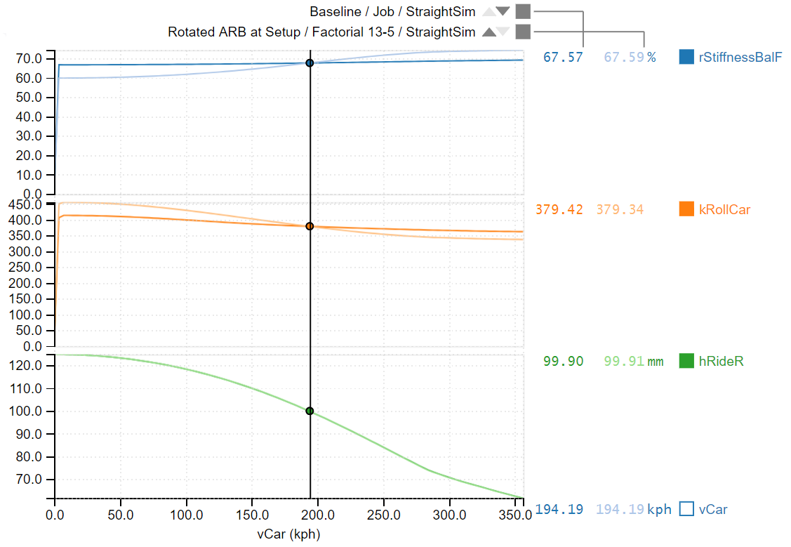
Figure 4: Mechanical balance and roll stiffness through the speed range
We’ve matched our high speed balance, but how does this help our low speed through corner balance? If we look at ΔrLatBalF (difference in mechanical balance between baseline and rotated ARB at setup) through Turn 13 and the last chicane in Barcelona (Figure 5), we can see that on entry the mechanical balance is slightly forwards of the baseline (less front grip and more rear mechanical grip) which gives us a more stable car when the driver stamps on the brakes. As the car slows down and the driver wants to turn in, the mechanical balance is now 2% rearwards of the baseline which allows the rear to resist more of the rolling moment of the car; the result being a more even lateral weight balance at the front tyres, resulting in less front locking and more front grip. At mid corner the mechanical balance is up to 6% rearwards (cursor position), giving a big improvement in front grip when the driver is trying to turn the car (less low speed mid corner understeer).
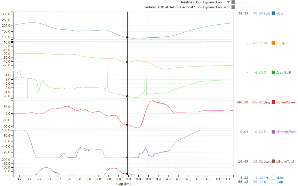
Figure 5: Mechanical balance change through corner (ΔrLatBalF)
Unfortunately, as with everything in F1, this doesn’t come without a downside; as the driver applies initial throttle to accelerate out of the corner, there is less rear grip until the car has gained some speed, which could make the car slightly more nervous on initial traction. However, the gains through entry and mid corner in this example are enough to leave us 51ms ahead at the end of the lap with a happier and more confident driver. Not bad for a morning’s work!
Of course we could approach this problem from another angle. As a race engineer you might decide that the best way to fix this problem is to move mechanical balance rearwards at low speed mid corner relative to entry/exit, while preserving high speed mechanical balance. In this case you could highlight runs on the parallel coordinates plot where in high speed Turn 9, the mechanical balance is similar or slightly forwards of the baseline, while in low speed Turn 10, mechanical balance is rearwards. It is very satisfying that this method produces the same end result.
If you are interested in finding out more about Canopy Simulations please contact us at hello@canopysimulations.com